Home >
Integrated Circuits >
Microprocessors >
80 Series
8251A USART Datasheet
Photograph

Features
- Single Chip USART
- Synchronous Communication up to 64 kbaud
- Asynchronous Communication up to 39.4 kbaud
- Transmitting / Receiving Operations with Double Buffered Configuration
- Error Detection (Parity, Overrun and Framing)
- Fully TTL/CMOS Compatible
Pin Layout

Pin Description
| Pin Number | Description |
|---|---|
| 1 | D2 - Data Bit 2 |
| 2 | D3 - Data Bit 3 |
| 3 | RX - Receive |
| 4 | GND - Ground |
| 5 | D4 - Data Bit 4 |
| 6 | D5 - Data Bit 5 |
| 7 | D6 - Data Bit 6 |
| 8 | D7 - Data Bit 7 |
| 9 | TXC - Transmit Clock Input (Active Low) |
| 10 | WR - Write (Active Low) |
| 11 | CS - Chip Select (Active Low) |
| 12 | C/D - Command/Data Select |
| 13 | RD - Read (Active Low) |
| 14 | RXRDY - Read Register Ready |
| 15 | TXRDY - Transmitter Register Ready |
| 16 | SYNDET/BD - See Datasheet |
| 17 | CTS - Clear To Send (Active Low) |
| 18 | TXEMPTY - Transmitter Register Empty |
| 19 | TXD - Transmit Output |
| 20 | CLK - Clock |
| 21 | RESET - Reset |
| 22 | DSR - Data Set Ready (Active Low) |
| 23 | RTS - Request to Send (Active Low) |
| 24 | DTR - Data Terminal Ready (Active Low) |
| 25 | RXC - Receive Clock (Active Low) |
| 26 | Vcc - Positive Supply |
| 27 | D0 - Data Bit 0 |
| 28 | D1 - Data Bit 1 |
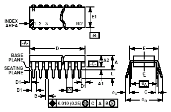
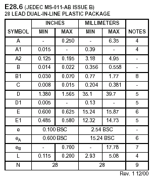
Dimensional Drawing


Technical Data
Datasheet
Application Notes


 Integrated Circuits