Home >
Integrated Circuits >
Special Function >
Intersil
ICL7109 12-Bit Micro Compatible A/D Converter Datasheet
Photograph

Product Details
- 12-Bit Binary Dual Slope Integrating Analog-to-Digital Converter
- Byte-Organized, TTL Compatible Three-State Outputs
- RUN/HOLD Input and STATUS Output Can Be Used to Monitor and Control Conversion Timing
- True Differential Input and Differential Reference
- Operates At Up to 30 Conversions/s
Pin Layout

Pin Description
| Pin Number | Description |
|---|---|
| 1 | GND - Digital Ground |
| 2 | STATUS - Status of Analog Conversion |
| 3 | POL - Polarity |
| 4 | OR - Overrange |
| 5 | B12 - Output Bit (Most Significant) |
| 6 | B11 - Output Bit |
| 7 | B10 - Output Bit |
| 8 | B9 - Output Bit |
| 9 | B8 - Output Bit |
| 10 | B7 - Output Bit |
| 11 | B6 - Output Bit |
| 12 | B5 - Output Bit |
| 13 | B4 - Output Bit |
| 14 | B3 - Output Bit |
| 15 | B2 - Output Bit |
| 16 | B1 - Output Bit (Least Significant) |
| 17 | TEST - Test Function |
| 18 | LBEN - Low Byte Enable |
| 19 | HBEN - High Byte Enable |
| 20 | CE/LOAD - Chip Enable/Load |
| 21 | MODE - See Datasheet |
| 22 | OSC IN - Oscillator Input |
| 23 | OSC OUT - Oscillator Output |
| 24 | OSC SEL - Oscillator Select |
| 25 | BUF OSC OUT - Buffered Oscillator Output |
| 26 | RUN/HOLD - A/D Conversion |
| 27 | SEND - Data Send Signal Input |
| 28 | V- - Analog Negative Supply |
| 29 | REF OUT - Reference Voltage Output |
| 30 | BUFFER - Buffer Amplifier Output |
| 31 | AUTO-ZERO - Auto-Zero Mode |
| 32 | INTEGRATOR - Integrator Output |
| 33 | COMMON - Analog Common |
| 34 | INPUT LO - Differential Input Low |
| 35 | INPUT HI - Differential Input High |
| 36 | REF IN + - Differential Input Reference (Positive) |
| 37 | REF CAP + - Reference Capacitor (Positive) |
| 38 | REF CAP - - Reference Capacitor (Negative) |
| 39 | REF IN - - Differential Input Reference (Negative) |
| 40 | V+ - Positive Supply Voltage |
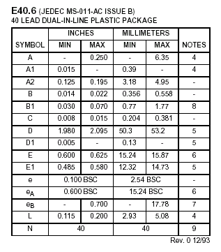
Dimensional Drawing


Technical Data
Datasheet
| Intersil - Datasheet for ICL7109 |
|
Application Notes


 Integrated Circuits