

Departments
 Integrated Circuits
Need Help
Home >
Integrated Circuits >
Special Function >
Intersil
ICL7129 4+1/2 Digit LCD Display, A/D Converter
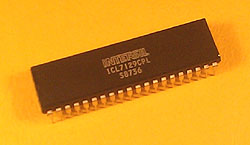
Photograph
Features
- ±19,999 Count A/D Converter Accurate to ±4 Count
- 10µV Resolution on 200mV Scale
- 110dB CMRR
- Direct LCD Display Drive
- True Differential Input and Reference
- Low Power Consumption
- Decimal Point Drive Outputs
- Overrange and Underrange Outputs
- Low Battery Detection and Indication
- 10:1 Range Change Input
Pin Layout
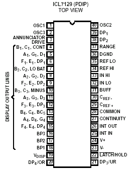
Pin Description
| Pin Number | Description |
|---|---|
| 1 | OSC1 - Oscillator |
| 2 | OSC3 - Oscillator |
| 3 | ANN - Annuciator Drive |
| 4 | B1,C1,CONT - Output to Display Segments |
| 5 | A1,G1,D1 - Output to Display Segments |
| 6 | F1,E1,DP1 - Output to Display Segments |
| 7 | B2,C2,LO BATT - Output to Display Segments |
| 8 | A2,G2,D2 - Output to Display Segments |
| 9 | F2,E2,DP2 - Output to Display Segments |
| 10 | B3,C3,MINUS - Output to Display Segments |
| 11 | A3,G3,D3 - Output to Display Segments |
| 12 | F3,E3,DP3 - Output to Display Segments |
| 13 | B4,C4,BC5 - Output to Display Segments |
| 14 | A4,D4,G4 - Output to Display Segments |
| 15 | F4,E4,DP4 - Output to Display Segments |
| 16 | BP3 - Backplane 3 |
| 17 | BP2 - Backplane 2 |
| 18 | BP1 - Backplane 1 |
| 19 | Vdisp - Negative Rail for Display |
| 20 | DP4/OR - See Datasheet |
| 21 | DP3/UR - See Datasheet |
| 22 | LATCH/HOLD - See Datasheet |
| 23 | V- - Negative Supply |
| 24 | V+ - Positive Supply |
| 25 | INT IN - Integrator Input |
| 26 | INT OUT - Integrator Output |
| 27 | CON - Continuity |
| 28 | COMMON - Common Mode Voltage |
| 29 | Cref+ - Reference Capacitor |
| 30 | Cref- - Reference Capacitor |
| 31 | BUFFER - Buffer |
| 32 | IN LO - Negative Input |
| 33 | IN HI - Positive Input |
| 34 | REF HI - Reference High |
| 35 | REF LO - Reference Low |
| 36 | DGND - Digital Ground Reference |
| 37 | RANGE - Range Setting |
| 38 | DP2 - Decimal Point 2 |
| 39 | DP1 - Decimal Point 1 |
| 40 | OSC2 - Oscillator |
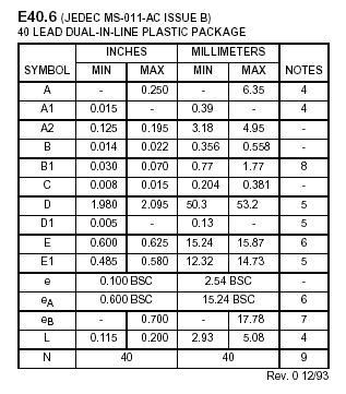
Dimensional Drawing

Technical Data