Home >
Integrated Circuits >
Microcontrollers >
Atmel
ATmega128 64-Pin 16MHz 128kb Microcontroller Datasheet
Photograph

Features
- Utilizes the AVR RISC Architecture
- High-performance and Low-power 8-bit RISC Architecture
- - 133 Instructions - Most Single Clock Cycle Execution
- - 32 x 8 General Purpose Working Registers
- - Up to 16 MIPS Throughput at 16MHz
- - Fully Static Operation
- - On-chip 2-cycle Multiplier
- Data and Nonvolatile Program Memory
- - 128k Bytes of In-System Self-Programmable Flash
- - Optional Boot Code Section with Independent Lock Bits
- - 4K Bytes EEPROM
- - 4K Bytes Internal SRAM
- - Programming Lock for Software Security
- - Up to 64K Bytes Optional External Memory Space
- JTAG Interface
- - Boundary-scan Capabilities According to the JTAG Standard
- - Extensive On-chip Debug Support
- - Programming of Flash, EEPROM, Fuses, and Lock Bits through the JTAG Interface
- Peripheral Features
- - On-chip Analog Comparator
- - Programmable Watchdog Timer with Separate On-chip Oscillator
- - Master/Slave SPI Serial Interface
- - Two 8-bit Timer/Counters with Separate Prescalar, Compare
- - Two Expanded 16-bit Timer/Counter with Separate Prescaler, Compare and Capture mode
- - Real Time Counter with Separate Oscillator
- - Six PWM Channels with Programmable Resolution from 1 to 16 Bits
- - Dual Programmable Serial USARTs
- - 8-channel, 10-bit ADC
- - Byte-oriented Two-wire Serial Interface
- Special Microcontroller Features
- - Power-on Reset and Programmable Brown-out Detection
- - Internal Calibrated RC Oscillator
- - External and Internal Interrupt Sources
- - Six Sleep Modes: Idle, ADC Noise Reduction, Power-save, Power-down, Standby, and Extended Standby
- - Software selectable Clock Frequency
- - ATmega103 Compatibility Mode Selected by a Fuse
- - Global Pull-up Disable
- I/O and Packages
- - 53 Programmable I/O Lines
- - 64-lead TQFP, and 64-pad MLF
- Operating Voltages
- - 4.5-5.5V for ATmega128
- Speed Grades
- - 0-16MHz for ATmega128
Pin Layout

Pin Description
| Pin Number | Description |
|---|---|
| 1 | PEN - Programming Enable |
| 2 - 9 | PE0-PE7 - Port E |
| 10 - 17 | PB0-PB7 - Port B |
| 18 | TOSC2/PG3 |
| 19 | TOSC1/PG4 |
| 20 | RESET |
| 21 | Vcc - Positive Power Supply |
| 22 | GND - Ground |
| 23 | XTAL2 - Crystal |
| 24 | XTAL1 - Crystal |
| 25 -32 | PD0-PD7 - Port D |
| 33 | PG0 (WR) |
| 34 | PG1 (RD) |
| 35 -42 | PC0-PC7 - Port C |
| 43 | PG2 (ALE) |
| 44 -51 | PA7-PA0 - Port A |
| 52 | Vcc - Positive Power Supply |
| 53 | GND - Ground |
| 54 - 61 | PF7-PF0 - Port F |
| 62 | AREF - Analog Reference |
| 63 | GND - Ground |
| 64 | AVCC - Analog Power Supply |
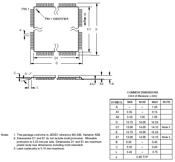
Dimensional Drawing

Technical Data
Datasheet
| Microchip Web Site - Datasheet for ATmega128 |
|
Application Notes
| Microchip Web Site - ATmega128 Application Notes |
|


 Integrated Circuits